
Mastering blueprint reading doesn't mean memorizing hundreds of obscure symbols before you ever touch a piece of metal. In fact, most welders spend years relying on just a core subset of concepts that carry the heaviest workload on any shop floor. By focusing on the vital few elements that matter most, you can demystify complex technical drawings and start interpreting fabrication plans with confidence on day one.
The 80/20 Rule, or Pareto Principle, suggests that 80% of your results come from 20% of your efforts. When applied to welding prints, this means that a handful of core elements (such as basic weld symbols, tail notes, key dimensions, and arrow orientation) cover the vast majority of what you will encounter on the job. Once you crack this foundational code, you can effortlessly navigate standard drawings, avoid costly fabrication errors, and focus your energy on what you do best: laying down clean, precise welds.
The 80/20 Concept in Metal Fabrication
Drawing standards are repetitive because shop problems are repetitive. Every print exists to answer five core questions:
- What is the part?
- Where are its features located?
- How big is it?
- How tight are the tolerances?
- How is it joined together?
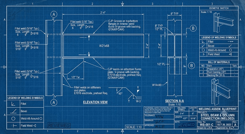
Since these core needs never change, the same set of conventions appears across everything from massive structural frames to simple pipe hangers. Rather than memorizing every obscure callout in the AWS or ASME handbooks, focus on the handful of symbols that directly govern fit-up, material cutting, hole layouts, and pass/fail inspections. Effective blueprint reading isn't about memorizing dictionary-sized spec books; it is about avoiding costly shop rework.
The Command Center: Title Blocks, General Notes, and Lines
Every successful build starts with foundational context before looking at geometry:
- Title Blocks & Notes: Always review these first. They dictate overall units, global tolerances, material specifications, finish requirements, and relevant welding standards. Fabricators who skip these frequently build parts that meet physical dimensions but fail final inspection due to an unread general note.
- Line Types: Object lines define solid, visible edges; hidden lines reveal obscured features; centerlines mark axes of symmetry and hole locations. Misidentifying line types distorts your spatial understanding, leading to flipped parts or offset hole patterns. Developing a quick eye for line styles is a foundational step in practical blueprint reading.
Start with the title block and general notes because they set the rules for the entire blueprint. This includes units, tolerances, material, finish, and sometimes weld standard references. Fabricators skip this and then wonder why a part is right but still rejected.
Next, recognize common line types: object lines (visible edges), hidden lines (features you cannot see), and centerlines (axes for holes, radii, and symmetry). These are the rails everything else rides on, so misreading them can shift a hole pattern or flip a part.
Fit-Up Control: Size, Location, and Tolerance Dimensions
Confusing size and location dimensions in blueprint reading is a major source of shop issues. Size indicates "how big" a feature is (such as slot width, hole diameter, or plate width), whereas location defines "where" it belongs (such as center-to-center spacing or hole center-to-edge).
It is essential to monitor tolerances closely, even if they only appear in a general note. An absent tolerance callout does not indicate that any dimension is acceptable; rather, it remains subject to the print's default tolerance policy, directly impacting whether components fit together cleanly without requiring grinding, forcing, or field modifications.
Developing a practice of circling assembly-critical dimensions early on is highly effective. Focusing on base-to-centerline heights, mating face lengths, bolt-hole locations, and any dimensions prone to stacking across several components helps prevent real-world mismatches caused by dimensional drift.
Standard Feature and Hole Callouts in Fabrication Drawings
These common callouts appear frequently to efficiently communicate layout and machining requirements:
- Diameter symbols and hole sizes (marked by Ø and a number) precisely define round holes. They are used to configure your drill press or specify hole positions for layout.
- Center marks and centerlines pinpoint the exact positions of hole centers. These markings are vital for precise layouts and crucial for inspection verification.
- Radii, chamfers, and bevel notes define corner relief and edge preparation. These specifications are critical because inadequate edge preparation affects both fit-up and welding access.
Understanding these callouts is necessary to prep parts correctly, inspect incoming components, and avoid welding pieces that must be machined later.
Core Components of Welding Symbols
A standard weld symbol consists of three fundamental parts: the arrow, the reference line, and an optional tail, which together convey all necessary weld information. The positioning of these details either above or below the reference line is critical, as it directly dictates which side of the joint must be welded.
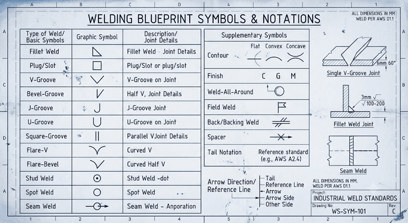
Prioritize mastering these essential weld symbol elements first:
- Start by learning the fillet weld symbol and its corresponding size callout. Since fillet welds are widely used in structural and general fabrication, this is the most practical symbol to master first.
- Next, grasp the difference between arrow-side and other-side placement, determined by whether the symbol is below or above the reference line. Getting this wrong can cause structural distortion, component interference, or inspection failures.
- After that, learn how to identify both-sides notations, where symbols appear on both sides of the reference line. This indication heavily impacts heat input control, welding sequence, and access planning.
- Lastly, learn to tell field welds apart from shop welds, and understand weld-all-around indicators. These notations completely change your workflow, tooling requirements, and build staging strategy.
A Structured Method for Fabricators to Read Blueprints
To identify vital project requirements when working under tight timelines, implement this reliable sequence:
- Examine the written specifications first. Review the title block, inspection callouts, and general notes. These define the baseline requirements for the entire project.
- Establish proper orientation. Locate every provided view (such as front, top, side, or section) and verify how they relate to one another before calculating measurements. Misinterpreting a view leads to wasted materials and lost productivity.
- Identify vital measurements. Mark out the dimensions and tolerances required for bolt-up alignment and mating components. These elements directly determine if the final assembly fits together properly.
- Analyze welding instructions at the end. Only inspect the weld symbols after gaining a clear understanding of the physical joint geometry. This approach allows you to determine physical access and organize your assembly sequence effectively.
Bridging the Gap From Booth to Blueprint
Although many professionals excel at laying down high-quality beads, their welding careers can plateau if they struggle to interpret blueprint specifications, especially when notes and symbols multiply across complex, multi-view drawings. To ensure students acquire booth proficiency along with the capacity to execute authentic operational directions, Arclabs integrates blueprint reading directly into its curriculum, paired with hands-on welding practice and employment readiness training.
Ready to transform your interest in welding into professional expertise? Call 877-647-4111 to speak with an admissions advisor about your training options. You can also reach out to us online with any questions. We will walk you through our hands-on welding programs and help you find the right fit for your goals.

